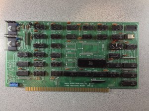
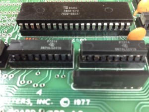
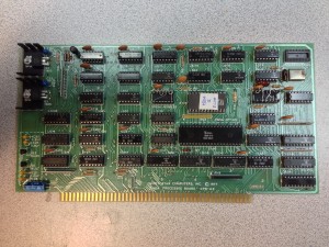
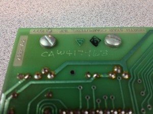
 The first board to tackle is the CPU board – part number ZPB-A2. The CPU board, the motherboard, and the chassis all have a number engraved – “CA W417963”.
Tasks performed on this board:
- Clean socketted IC pins with glass pen
- Test electrolytic and tantalum capacitors
- Clean edge connector
- Install EPROM circuitry
- Change boot address jumper block
 The legs on the ICs were quite corroded on this board (see pictures). Each one was removed from its socket, and given a quick brush with a glass pen (like this).
Next, I tested each of the electrolytic and tantalum capacitors. I used an ESR meter to check that the components were still within tolerance, as well as making sure that they had not developed any shorts. All of the capacitors passed, so the next step was to power up the board with a current-limited supply and allow it to warm up. The total draw on this board is 570mA.
 To address the biggest problem with resurrecting a NorthStar Horizon – how to make a boot disk – I needed to install a boot monitor that will allow me to hand-enter (or machine-enter over the serial port) a program to write an image using the disk controller. Following the instructions for the original CPU board, I populated the optional monitor ROM components.
The boot ROM lives at address EC00, so I had to adjust two sets of jumpers on the CPU board – the ROM base address, and the boot address. By default, the CPU board boots to address EB00 (a small boot PROM on the disk controller), but we need to boot the monitor at EC00. As you can see from the pictures, I’ve added headers to (hopefully) address the PROM and boot the right address.
Once the machine is complete and boot disks have been written, I can change the boot address back to EB00 to make the machine boot from floppy.

